
Electric circuits form the foundation of modern electrical engineering, enabling the flow of energy and signals. They consist of interconnected elements like resistors, capacitors, and inductors, which process electrical energy. Understanding circuit fundamentals is essential for designing and analyzing systems in technology. This section introduces the basic principles and components of electric circuits, providing a clear and comprehensive overview for students and professionals alike.
1.1 Definition and Importance of Electric Circuits
Electric circuits are interconnected paths through which electric currents flow, consisting of components like resistors, capacitors, and inductors. They are fundamental to modern technology, enabling the operation of electronic devices, power systems, and communication networks. Understanding electric circuits is crucial for designing and analyzing electrical systems, making them indispensable in engineering and technology. The textbook by Charles Alexander and Matthew Sadiku provides a comprehensive overview of these concepts, emphasizing their practical applications and theoretical foundations.
1.2 Brief History of Electric Circuit Development
The history of electric circuits traces back to early experiments with electricity, evolving through key discoveries by pioneers like Ohm and Kirchhoff. Their work laid the groundwork for circuit theory and analysis. Over time, advancements in components and tools, such as PSpice and MATLAB, revolutionized circuit design. The textbook by Charles Alexander and Matthew Sadiku chronicles this progression, from fundamental laws to modern applications, illustrating how electric circuits have become integral to technology and engineering.

Basic Concepts in Electric Circuits
Electric circuits involve electric charge, voltage, current, resistance, and Ohm’s Law. These concepts define power and energy, essential for understanding circuit behavior and design.
2.1 Electric Charge, Voltage, and Current
Electric charge is the fundamental property of matter, measured in coulombs. Voltage, or electric potential difference, drives current through a circuit. Current, measured in amperes, is the flow of charge. Ohm’s Law relates these quantities: V=IR. Understanding these basics is crucial for analyzing circuit behavior, as detailed in Fundamentals of Electric Circuits by Charles Alexander and Matthew Sadiku. These principles form the foundation of circuit theory and design.
2.2 Resistance and Ohm’s Law
Resistance is a measure of opposition to the flow of electric current, quantified by Ohm’s Law: V=IR. Materials like resistors exhibit resistance, while conductors offer less. Ohm’s Law relates voltage, current, and resistance, forming the basis of circuit analysis. Understanding resistance is crucial for designing circuits, as explained in Fundamentals of Electric Circuits. This principle helps predict voltage drops and ensures efficient energy transfer in electrical systems.
2.3 Power and Energy in Electric Circuits
Power in electric circuits represents the rate of energy transfer, calculated as P = VI, where V is voltage and I is current. Energy, the capacity to do work, is stored or dissipated in circuit elements like resistors. Understanding power and energy is vital for designing efficient systems, as explained in Fundamentals of Electric Circuits. These concepts ensure optimal performance and minimize energy loss in electrical systems, from simple DC circuits to complex AC applications.

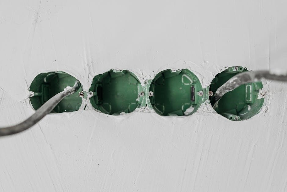
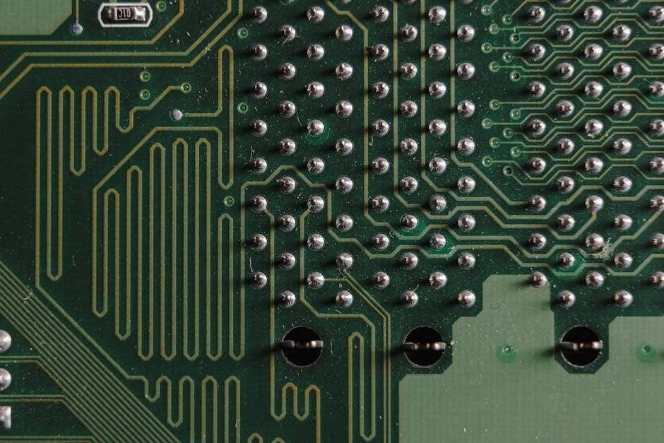
Circuit Elements
Circuit elements include resistors, capacitors, and inductors, which store or dissipate energy. Switches control current flow, while voltage and current sources provide energy to circuits.
3.1 Resistors, Capacitors, and Inductors
Resistors oppose current flow, capacitors store energy in electric fields, and inductors store energy in magnetic fields. Resistors are essential for voltage division and current limiting, while capacitors are used for filtering and energy storage. Inductors manage changes in current flow, reducing voltage spikes. These elements are fundamental in circuit design, enabling functions like signal processing, power supply regulation, and energy transfer. Understanding their behavior is crucial for analyzing and designing electric circuits effectively.
3.2 Switches, Sources, and Other Circuit Components
Switches control current flow by opening or closing circuits, while voltage and current sources provide energy to circuits. Ideal sources maintain constant voltage or current, whereas practical sources include internal resistance. Other components like diodes, transformers, and transistors perform specialized functions, such as rectification, voltage transformation, and amplification. These elements are essential for circuit functionality, enabling control, energy supply, and signal processing in various applications, from power systems to electronic devices.
Circuit Analysis Techniques
Circuit analysis involves methods like Kirchhoff’s laws, node and mesh analysis, and Thevenin/Norton theorems to solve for voltages and currents. Tools like PSpice and MATLAB aid in simulations and validations, ensuring accurate circuit behavior predictions and optimizations.
4.1 Kirchhoff’s Voltage and Current Laws
Kirchhoff’s Voltage Law (KVL) states that the sum of voltage changes around a closed loop in a circuit equals zero. Kirchhoff’s Current Law (KCL) states that the sum of currents entering a junction equals the sum leaving it. These laws are fundamental tools in circuit analysis, enabling engineers to solve complex networks by breaking them into manageable loops and nodes. They apply universally, forming the basis for more advanced techniques in electrical engineering and circuit design.
4.2 Node and Mesh Analysis
Node and Mesh Analysis are powerful techniques for solving complex electric circuits. Node Analysis applies Kirchhoff’s Current Law to determine voltages at circuit nodes, while Mesh Analysis uses Kirchhoff’s Voltage Law to find currents in closed loops. These methods offer systematic approaches to circuit analysis, reducing intricate networks to manageable systems of equations. They are invaluable for both educational purposes and professional applications, providing clarity in understanding and designing electrical systems. Their application extends to modern tools like PSpice and MATLAB for advanced simulations.

Series and Parallel Circuits
Series circuits connect components end-to-end, sharing the same current, while parallel circuits connect components across the same two nodes, sharing the same voltage. Understanding these configurations is fundamental for analyzing and designing efficient electrical systems, ensuring proper voltage and current distribution in various applications, from power systems to electronic devices. This section explores their characteristics, advantages, and practical uses in detail.
5.1 Characteristics of Series Circuits
In a series circuit, components are connected end-to-end, creating a single path for current flow. The current remains the same throughout the circuit, while voltage drops occur across each component. Total resistance is the sum of individual resistances, and if one component fails, the entire circuit is disrupted. Series circuits are commonly used in applications like simple LED circuits or toasters, where a single control point is desired. Understanding their behavior is crucial for designing efficient electrical systems.
5;2 Characteristics of Parallel Circuits
In parallel circuits, components are connected across the same two points, creating multiple paths for current flow. Voltage remains constant across all branches, while current divides among them. Total resistance is less than the smallest individual resistance, and if one component fails, others continue functioning. Parallel circuits are widely used in household wiring and electronic devices, ensuring reliable operation and minimizing the risk of complete system failure. They are essential for modern electrical systems, offering flexibility and redundancy.
AC and DC Circuits
AC and DC circuits are fundamental in electrical engineering, with AC (alternating current) periodically reversing direction and DC (direct current) flowing steadily in one direction. Understanding their principles and applications is crucial for designing modern electrical systems, from power distribution to electronic devices. This section explores the basics of both circuit types, their differences, and their roles in technology.
6.1 Fundamentals of DC Circuits
Direct Current (DC) circuits involve the unidirectional flow of electric charge, driven by sources like batteries. These circuits are foundational, consisting of resistors, capacitors, and inductors. Ohm’s Law governs the relationship between voltage, current, and resistance. Kirchhoff’s Laws enable analysis of complex DC networks. Capacitors store energy temporarily, while inductors oppose sudden current changes. DC circuits power electronic devices, from simple LED circuits to complex power supplies, making them essential in modern technology and engineering applications.
Alternating Current (AC) circuits involve the periodic reversal of electric charge flow, typically represented by a sine wave. AC circuits are fundamental in power distribution systems due to their efficiency in long-distance transmission. Key concepts include frequency, phase, and impedance, which govern the behavior of AC signals. Understanding AC circuits is crucial for analyzing systems like household appliances, audio equipment, and communication devices. They enable the efficient transfer of energy and are essential in modern electrical engineering applications.

Thevenin and Norton Theorems
Thevenin and Norton Theorems simplify complex circuit analysis by converting circuits into equivalent forms. These theorems are essential tools for engineers to analyze and design circuits efficiently.
7.1 Thevenin’s Theorem
Thevenin’s Theorem simplifies complex circuit analysis by converting any linear electrical network into an equivalent circuit with a single voltage source and a series resistor. This theorem is particularly useful for analyzing circuits with multiple sources and loads. It states that the voltage across any load can be determined by replacing the network with a Thevenin-equivalent circuit, making it easier to understand and compute circuit behavior without unnecessary complexity. Engineers widely use this concept for efficient circuit design and troubleshooting.
7.2 Norton’s Theorem
Norton’s Theorem provides a method to simplify complex circuits by converting them into an equivalent circuit with a single current source and a parallel resistor. This theorem is particularly useful for circuits with multiple loads or sources. It allows engineers to analyze and compute circuit behavior more efficiently by reducing the network to its Norton-equivalent form. The theorem is widely applied in circuit design and troubleshooting, offering a powerful tool for understanding and optimizing electrical systems.
Applications of Electric Circuits
Electric circuits are fundamental to power systems, electronics, telecommunications, and signal processing. They enable energy distribution, communication, and control in modern technology, driving innovation and development.
8.1 Power Systems and Electronics
Power systems and electronics rely heavily on electric circuits for efficient energy distribution and utilization. From household appliances to industrial machinery, circuits play a crucial role in converting and managing electrical energy. Electronics, including microprocessors and communication devices, depend on circuit design for functionality. Understanding circuit fundamentals is essential for developing sustainable and innovative power solutions, ensuring reliable energy supply and advancing technological capabilities in various industries.
8.2 Telecommunications and Signal Processing
Electric circuits are vital in telecommunications and signal processing, enabling the transmission and manipulation of electrical signals. Circuit elements like resistors, capacitors, and inductors are used to filter, amplify, and modulate signals. These circuits are essential for wireless communication, data transmission, and audio processing. Advances in circuit design have enhanced signal integrity and noise reduction, ensuring reliable performance in modern telecommunication systems. The use of simulation tools like MATLAB and PSpice aids in designing and analyzing complex signal processing circuits efficiently.
Safety in Electric Circuits
Safety in electric circuits is crucial to prevent shocks, fires, and equipment damage; Proper precautions, like using protective gear and circuit protection devices, ensure safe operation and maintenance.
9.1 Electrical Hazards and Precautions
Electric circuits pose risks such as shocks, burns, and equipment damage. Common hazards include live wires, overloaded circuits, and improper grounding. To ensure safety, use insulated tools, avoid wet conditions, and de-energize circuits before maintenance. Proper protective equipment like gloves and goggles is essential. Regular inspections and adherence to safety standards minimize risks. Understanding circuit behavior and following precautions can prevent accidents, ensuring safe operation and maintenance of electrical systems.
9.2 Circuit Protection Devices
Circuit protection devices are essential for safeguarding electrical systems from damage caused by overcurrent, short circuits, or voltage spikes. Fuses, circuit breakers, and surge protectors are common devices used to interrupt abnormal current flows. Fuses melt when current exceeds a safe level, while circuit breakers trip to disconnect power. These devices prevent equipment damage, reduce fire risks, and ensure user safety. Proper installation and maintenance of these devices are critical for reliable circuit operation and protection.
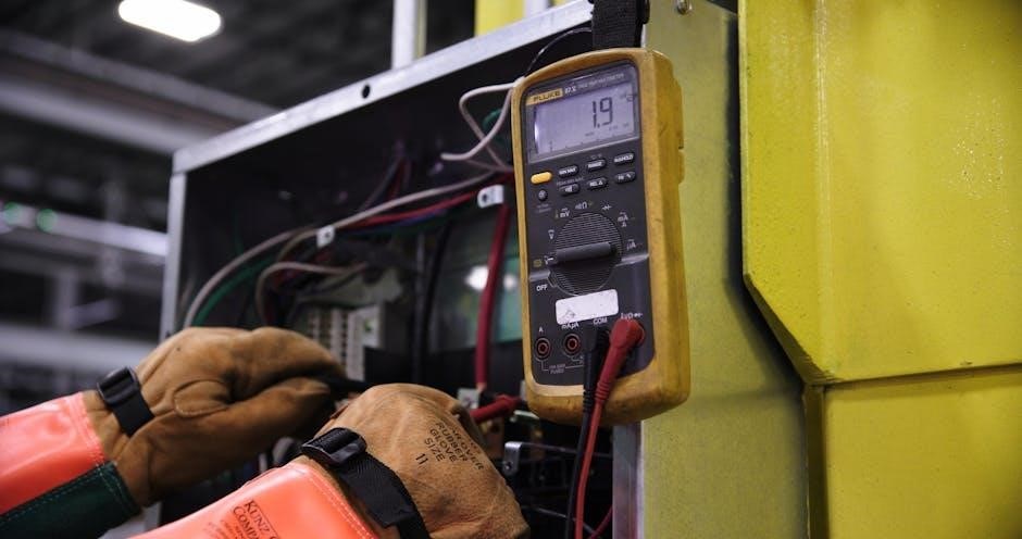
Tools for Circuit Analysis
PSpice and MATLAB are essential tools for simulating and analyzing electric circuits. These software platforms enable users to test circuit behavior, perform complex calculations, and visualize results efficiently.
10.1 PSpice and Simulation Software
PSpice is a powerful simulation tool for analyzing electric circuits, offering schematic capture, simulation, and waveform analysis. It supports DC, AC, and transient analysis, enabling users to test circuit behavior virtually. This software is widely used in education and industry for designing, troubleshooting, and optimizing circuits. It also integrates with MATLAB for advanced analysis. PSpice’s user-friendly interface and comprehensive libraries make it an essential tool for engineers and students to explore circuit dynamics and verify theoretical concepts practically.
10.2 MATLAB for Circuit Analysis
MATLAB is a powerful tool for circuit analysis, offering robust computational and graphical capabilities. It enables engineers to simulate and analyze electric circuits, solve complex equations, and visualize results. MATLAB supports circuit theory applications, including AC/DC analysis, filter design, and signal processing. Its scripting language and extensive libraries make it ideal for prototyping and research. Widely used in academia and industry, MATLAB enhances the understanding of circuit behavior and facilitates innovative solutions in electrical engineering.

Real-World Engineering Applications
Electric circuits are integral to modern technology, powering systems in telecommunications, electronics, and energy distribution. They enable innovation in devices, communication networks, and industrial control systems, driving technological advancement.
11.1 Circuit Design in Modern Technology
Circuit design is pivotal in modern technology, from consumer electronics to communication systems. The fundamentals of electric circuits, as detailed in resources like Fundamentals of Electric Circuits by Charles Alexander and Matthew Sadiku, underpin innovations in power systems, telecommunications, and renewable energy. Modern tools like PSpice and MATLAB enable engineers to simulate and optimize circuit performance, ensuring efficiency and reliability in cutting-edge applications. This integration of theory and practice drives advancements in technology and engineering.
11.2 Career Opportunities in Electric Circuits
Electric circuits expertise opens doors to diverse career opportunities in engineering and technology. Professionals can pursue roles as circuit design engineers, power systems engineers, or telecommunications engineers. The fundamentals of electric circuits, as explored in texts like Fundamentals of Electric Circuits, equip individuals for roles in industries such as electronics, renewable energy, aerospace, and automotive. With advancements in technology, demand for skilled engineers in circuit design and analysis continues to grow, offering rewarding career paths in both established and emerging fields.

Future Trends in Electric Circuits
Emerging technologies like nanotechnology, green energy, and advanced materials are reshaping electric circuits. These innovations promise smaller, more efficient, and sustainable circuit designs, driving future advancements in electronics.
12.1 Emerging Technologies in Circuit Design
Emerging technologies like nanotechnology, graphene, and quantum computing are revolutionizing circuit design. These advancements enable smaller, faster, and more energy-efficient circuits. Green energy solutions and IoT integration are also driving innovation, ensuring sustainable and interconnected systems. AI-powered design tools optimize circuit performance, while flexible and printable electronics open new possibilities for wearable devices. These technologies are shaping the future of electric circuits, making them integral to next-generation applications in fields like healthcare, telecommunications, and renewable energy.
12.2 Sustainability in Electric Circuits
Sustainability in electric circuits focuses on minimizing power consumption and maximizing energy efficiency. Modern designs prioritize low-power components and renewable energy integration. Eco-friendly materials and manufacturing processes reduce environmental impact. Energy harvesting techniques and smart grid technologies optimize resource usage. These practices ensure circuits are environmentally responsible and aligned with global sustainability goals, as highlighted in resources like Fundamentals of Electric Circuits, which emphasize green technology applications.